
April 10, 2018
Test Equipment You Can Build ...
~ Signal Generator "SigGen" Test Gadget ~
Frequency generation is at the core of Amateur Radio ... And here's a start for getting your hands around
using a DDS chip and an Si5351 chip in your Test Gadget!
Welcome!
Signal generators (synthesizers) have been at the very core of every ham's interest and communication mode since the dawn of Amateur Radio. In this episode we add a "Signal Generator Test Gadget to our line-up of little modules in our Test Equipment You Can Build series. Just plug in this new DDS-60 based module to our standard Arduino baseboard controller, add the simple illustrative sketch (software) to it, and you'll be off to the races! Also check out the other siggen modules (Si5351 and an offshore AD9851 DDS module), as well as the evolving Gagdet Rack software from AD7JT that controls each of the Gadgets as we continue evolving the platform.
73, George N2APB, Joe N2CX and Dave AD7JT
Listen to Podcast ... (Click to play, or right-click to download and save)
CWTD Episode #87: Test Equipment You Can Build ... The Signal Generator "SigGen" Test Gadget
Background
Old days – spark gaps and Alexanderson Alternator – used for high power transmitters.
Vacuum tubes made low power oscillators practical
Most common types were Armstrong, Colpitts and Hartley.
Usually used fixed inductors and variable capacitors
Made possible sensitive, selective receivers as well as transmitters
Stability highly dependent on quality and construction of LC components
Also, audio sources using Wein bridge and various other RC components to set frequency
Square wave generators such as astable oscillators for digital circuits
WWII era saw development of quartz crystals as frequency determining elements
Greatly enhanced stability and made multi-channel radios practical
Development of transistors in the late 50’s allowed low power (and portable) radios practical
Still used same configurations and tuning elements as vacuum tubes
LC, crystal controlled and same audio circuits
New semiconductor and integrated circuits in the 60's fueled explosion of oscillator architectures
Voltage variable capacitors (VVC) provided electronic variable tuning
Integrated circuit oscillator chips circumvented LC tuning
AD8308 function generator, NE555 timer/square wave generator
CMOS and ECL inductorless RF VCOs
Digital phase comparators and digital dividers made phase locked loops more practical
NE556, NE557 early designs – many more later
Synthesizer chip examples:
AD985X series – External clock osc. Digitally synthesized sine output
Si570 – internal XO with VCXO and digital pll synthesis functions
Si5351 – internal XO, with VCXO and digital pll synthesis functions
Plus multiple independent outputs
Signal generators and radio gear now incorporate synthesizers, PLL and DSP techniques due to the rise of computing techniques, specifically microcontrollers
Three SigGen Gadgets
We've chosen to implement three different signal generation methods/modules:
1) QRP Labs' Synth Kit (Si5351) ... http://www.qrp-labs.com/synth
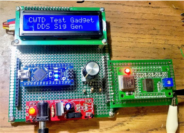
2) Midnight Design DDS-60 (AD9851) ... https://midnightdesignsolutions.com/dds60/index.html
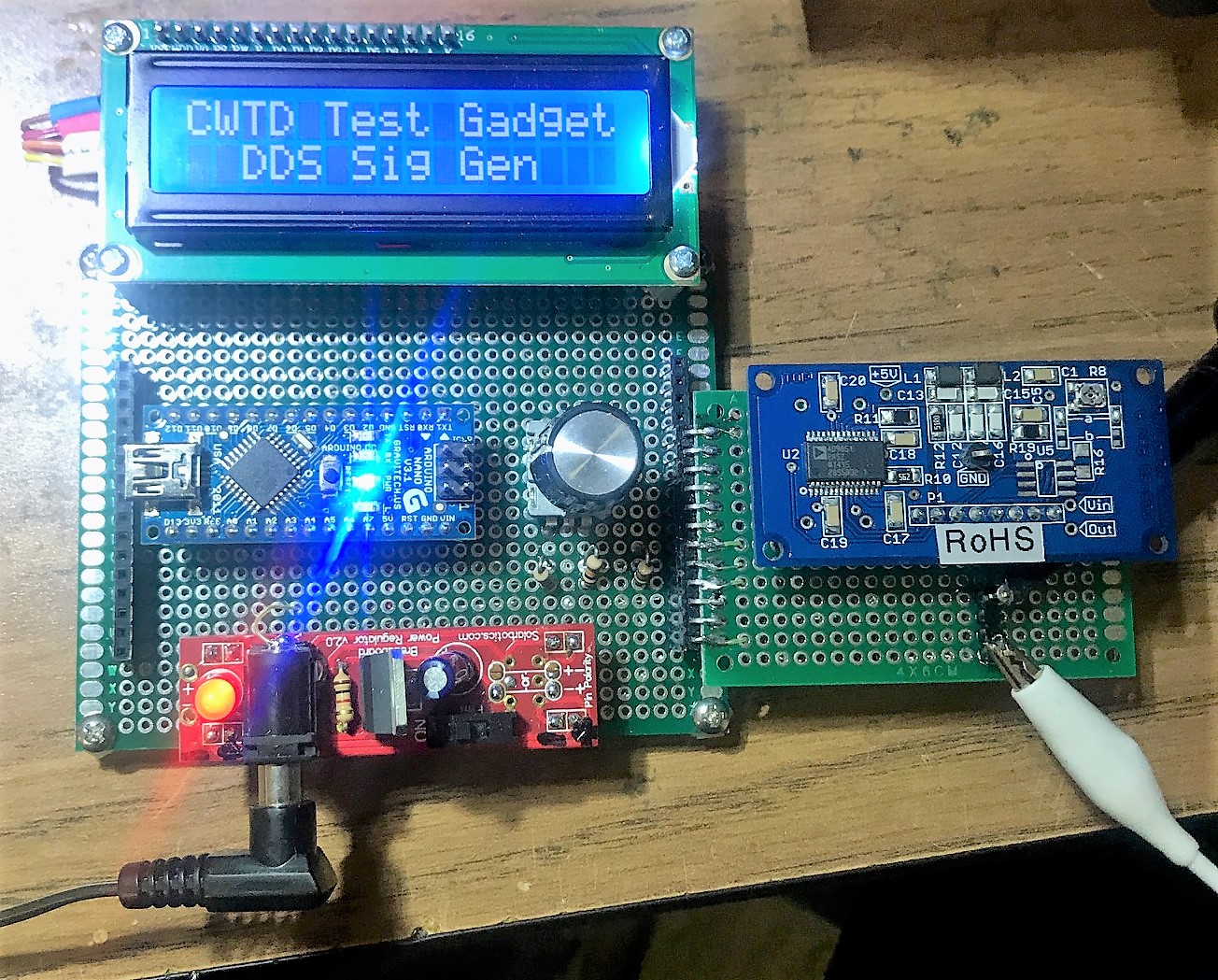
3) Offshore El Cheapo DDS Modules (AD9850 or AD98501 ... https://www.ebay.com/i/282003133703?chn=ps&dispItem=1
See the photos below showing each of the plug-in Gadgets for which we're developing software right now.
We chose these modules because chances are that most of us Chatters already have at least one of these siggen modules, either still in a kit bag, sitting on the bench, or plugged into another project. Hans Summer's nifty "Synth Kit" is used in his very cool U3S WSPR product -- just unplug it from the U3S and plug it into your Gadget! I've been selling the DDS-60 for years, and many people these days are going the route of ordering those "el cheapo" DDS modules off eBay. So again, chances are you have one of these three modules already.
And all you need to do is solder it onto one of the little green plugboards we've standardized on, wire up +12, Ground and the three control lines ... and bingo, it should work real nice with the software we have.
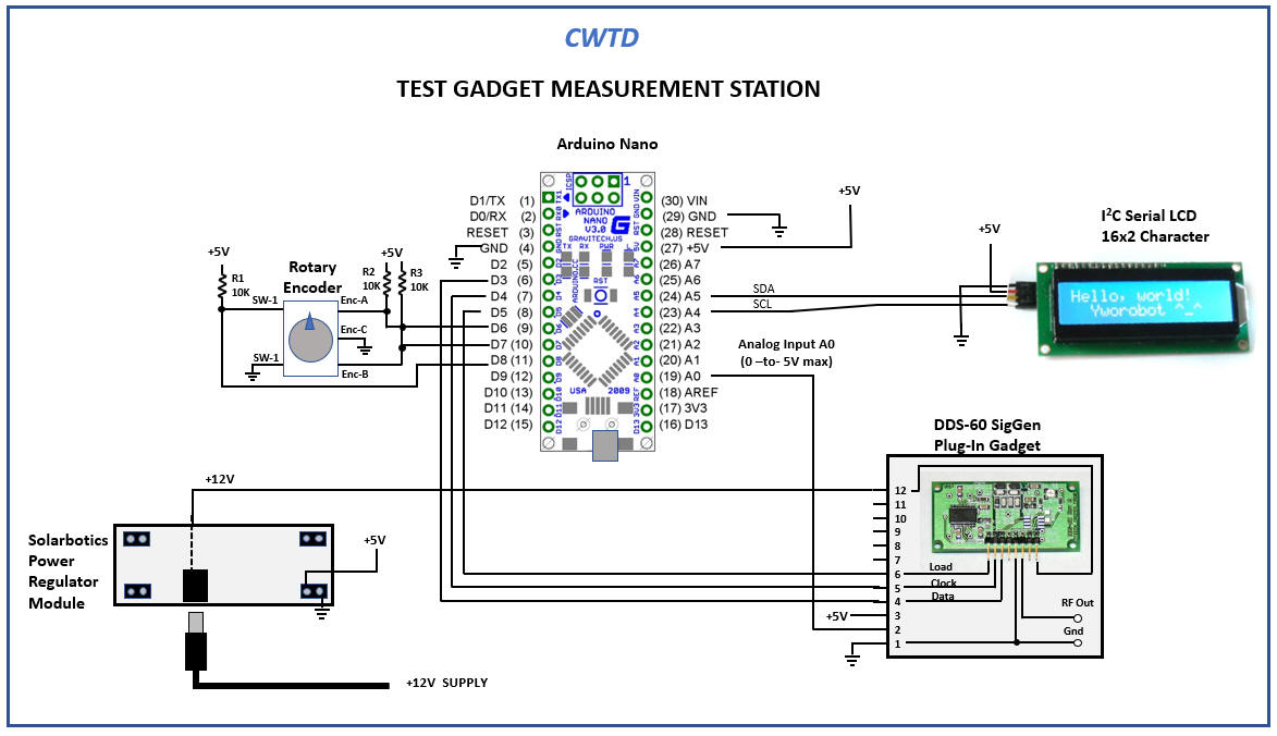
The Test Gadget: Motherboard + DDS-60 Plug-in:
(Click here to see underside for wiring of the DDS-60 Plug-in module)
The Test Gadget: Motherboard + Offshore DDS Plug-in:
(Click here to see underside for wiring of the DDS-60 Plug-in module), and the Schematic.
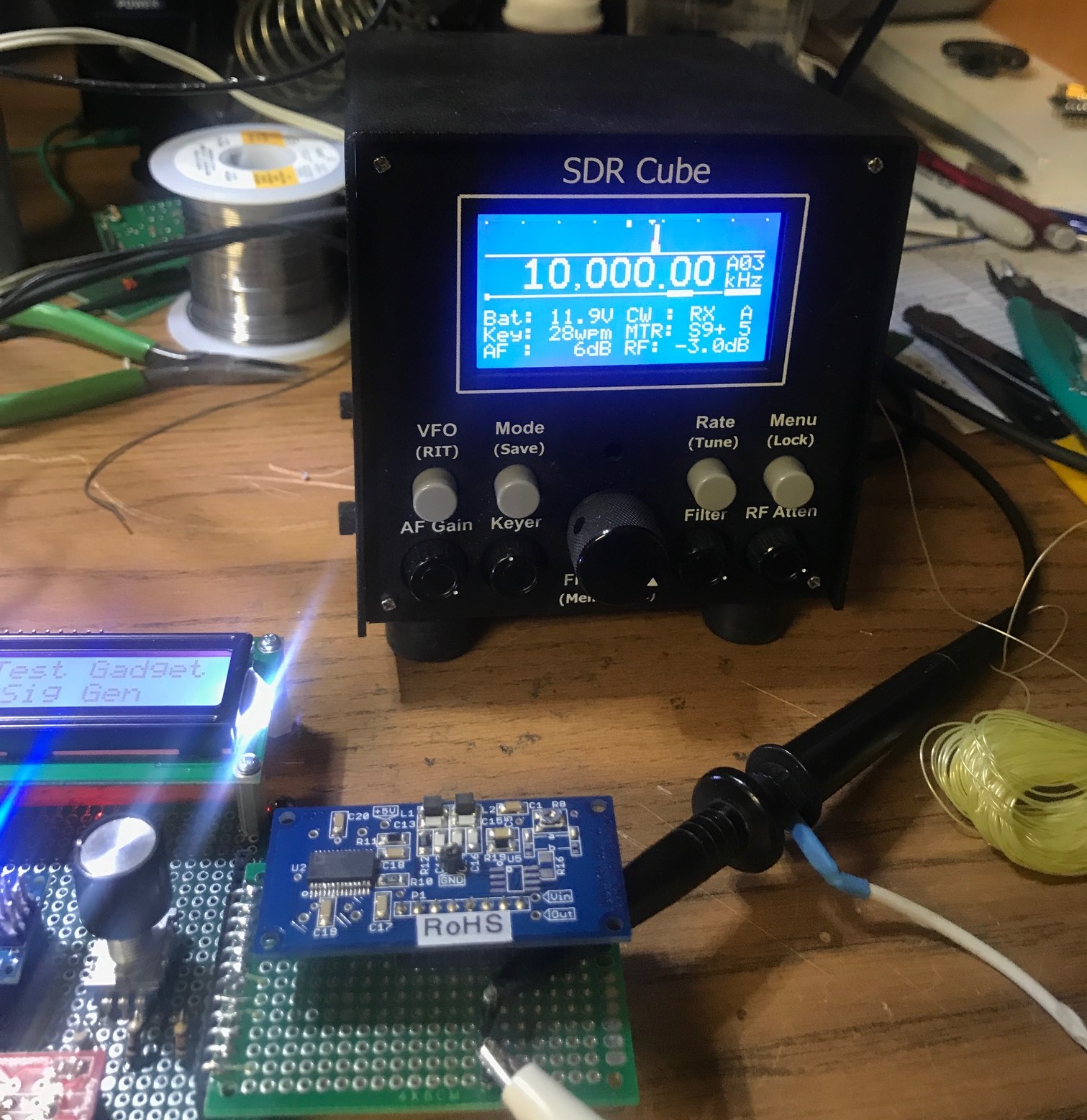
Demo (click photo below):
Test Gadget Schematic
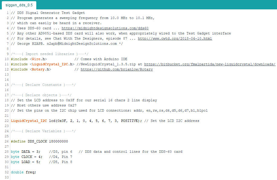
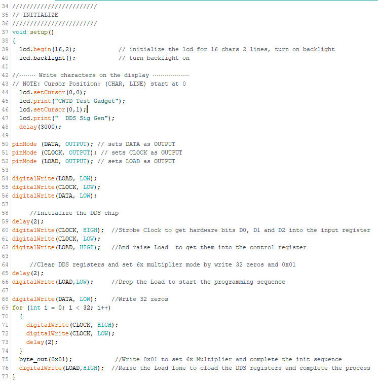
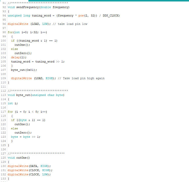
Simple SigGen Sketch ... (Download: siggen_dds_0.5.ino)
Special Treat ... The New Gadget Framework Sketch ... by Dave, AD7JT
The purpose of our initial "simple" sketches is to demonstrate how easy it is, in straightforward Arduino software, to achieve control of the Test Gadgets. Easy to understand, troubleshoot and get functional on your bench.
In preparation for the end-goal of having USABLE software for our Test Gadgets, Dave Collins, AD7JT has taken it upon himself to craft a flexible and extensible software framework that can grow with us as we add on many more Gadget plug-ins over time.
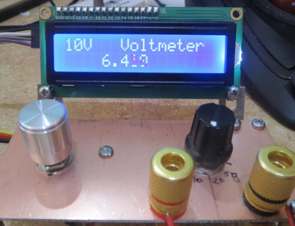
Dave's "Gadget Rack" sketch is downloadable now, and Dave will be going through it with us during this show. If you have your Test Gadget baseboard built up, you should download this and give it a try. It only has the Voltmeter Gadget programmed in, but take a look at the list of features it supports! ...
This version does the following:
Announces itself and displays firmware version at startup and pauses for 3 seconds.
Uses the built-in 1.1V analog reference voltage instead of Vcc.
Reduced the number of debug messages.
Calculates the volt meter range based on the reference voltage.
Uses a 10-point running average and requires a 1% change to update the display to reduce the LCD updates.
Initializes to the highest voltmeter range setting.
Improved the display appearance.
I have not updated the voltage divider but I plan on going to five switch settings (because that's what my switch has). With the old resistor values I get the following four ranges:
1.10 V
2.20V
5.50V
11.00V
With new resistor values I am planning for the following ranges:
2.50V
5.00V
10.00V
25.00V
50.00V
These ranges can be achieved using standard 1% resistor values.
