
May 8, 2018
Test Equipment You Can Build ...
~ RF Power Measurement Test Gadget ~
Let's measure some power with a simple RF Detector Test Gadget!
Welcome!
The topic this time is RF Power Measurement, using a new simple plug-in Test Gadget that we're adding to our Arduino base board. When coupled with the DDS Siggen gadget built last month, we can now squirt some RF into a test circuit (LPF, amplifier, L/C/R network, whatever) and then measure its response, providing some great indicators of that circuit's performance. This capability forms the basis of a simple scalar network analyzer (SNA) that can be enhanced in any number of ways, as dictated by the needs of your own bench!
73, George N2APB, Joe N2CX and Dave AD7JT
CWTD Episode #88: Test Equipment You Can Build ... The RF Power Measurement Test Gadget
Background
Simple diode detector
Inaccurate at low levels due to diode drop
Ge ~ 0.2 to 0.3V
Si ~ 0.6V
Schottky ~ 0.3 to 0.4V
Loses accuracy below several volts of RF applied
Hi input Z
Compensated diode detector
Good down to about 50 mV input
High input Z
QST ref: Tandem Match – An Accurate Wattmeter, by John Grebenkemper, KA3BLO, QST, Jan 1987 pp, 18-26
Example - Accuprobe
Uses two Schottky diodes with DC feedback to compensate for low voltage non-linearity
Uses switch to bypass compensation for inputs above 5V rms
Accuprobe now sold by QRPkits
Log detector
Good down to microvolt levels and up to ~ 0 dBm
Analog Devices AD8307
Linear from -80 dBm (~22 mV rms) to +10 dBm (~.7 Vrms)


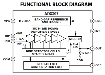

DC out ~ 25mV/dB
Not Hi input Z but good for 50 ohms
Tandem Match (QST for January 1987)
The Test Gadget Motherboard with RF Detector Gadget (left) and DDS-60 Siggen Gadget (right):
Test Gadget Schematic
REFERENCE: Previous CWTD Episode on LPF Filter Design & Measurement
Simple Power Meter Sketch ... (Download: rfpowergadget0.5.zip)
Gadget Framework Sketch ... by Dave, AD7JT
The purpose of our initial "simple" sketches is to demonstrate how easy it is, in straightforward Arduino software, to achieve control of the Test Gadgets. Easy to understand, troubleshoot and get functional on your bench.
In preparation for the end-goal of having USABLE software for our Test Gadgets, Dave Collins, AD7JT has taken it upon himself to craft a flexible and extensible software framework that can grow with us as we add on many more Gadget plug-ins over time.
Dave's "Gadget Rack v1.002" sketch is downloadable here
RF Power Meter Gadget ... by Dave, AD7JT
/**********************************************************
* rfpwrmeter.cpp - Simple RF power meter
* 2018-04-10
* Dave AD7JT
* ad7jt@cox.net
**********************************************************
* This gadget uses a simple, half-wave rectifier circuit
* to measure an RF waveform's peak voltage. It then uses
* the formula dB = 20*log(v/v0) to compute the relative
* power. The current input voltage level is v and v0 is
* the base power level. The base power level is read
* when the encoder switch is held closed (pressed) for
* one second or more. This calibrates the rf meter and
* all power readings will be relative to v0. The RF power
* meter presents a 50-ohm load to the input signal.
*
* The calibration level (v0) is arbitrary and is normally
* set to the level read when the RF source is fed directly
* into the RF power meter. Once the RF power meter is
* calibrated, a circuit/device such as a filter can be
* inserted between the RF source and the RF power meter
* to measure the device under test's (DUT) frequency
* response.
*
* The DUT may be tested at a specific frequency or across
* a range if frequencies. Note that RF sources and power
* meters may not be linear across all frequency ranges and
* it may be necessary to recalibrate the RF power meter
* at several or all test frequencies.
*
* If accurate power levels are required, the RF source
* power level must be set using other equipment to set it
* to the desired level. For example, a one milliwatt,
* sinusoidal, RF signal driving a 50-ohm load will have
*
* 1. a peak-to-peak amplitude of 0.632 volts which could be
* measured with a properly calibrated oscilloscope
*
* 2. an RMS voltage of 0.224 volts which could be measured
* with a sensitive DMM (Vac scale)
*
* 3. a half-wave peak voltage of 0.316 volts that could be
* at the cathode end of the RF meter's rectifying diode with
* a sensitive DMM (Vdc scale). (Note: you may have to compensate
* for the forward voltage drop of the rectifier diode.)
*
* 4. With 1 mw of input power, the dB readings will be in dBm.
* A reading of 0.0 will indicate 1 mw. Positive readings
* indicate the DUT has gain, negative readings will indicate
* the DUT has a loss at that frequency. Tables and formulas
* are available from many on-line sources to translate
* dBm and watts.
*


