Aug 7, 2012
Join the "CWTD Yahoo Group" for
email discussion in between our weekly sessions by clicking
here.
Toroids ... Selection, Construction and Use
A continuation in our Component Selection
series
Many times when we see plans for a good project we think
"Hey, I'd like to make this project but ..."
we don't have the exact parts called for. But if we dig around in the junk
box for parts we do have
we can often use them just fine by altering the project specs or schematic
accordingly.
This week's program focuses on ... Toroids!
Overview
Are you a bit fearful, or at least hesitant, when it comes
to dealing with toroids in your homebrew circuits? C'mon, tell the truth!
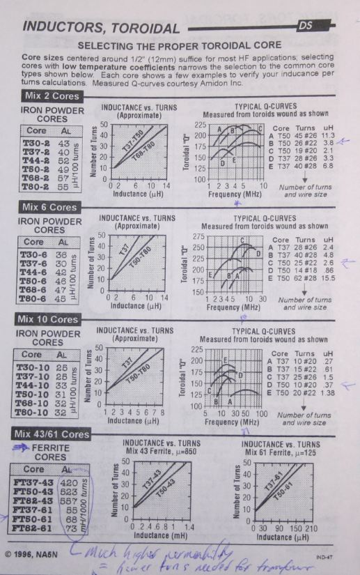
Whether it's confusion about the right size to use, the right color (err ... the
"mix" or "permeability", whatever that is), how to mount that wiggly component
on the board, or the numb fingertips from wrapping endless turns around that
little FT37 core ... then losing count after 40 and either counting them while
looking through a 100x magnifier or ripping all that wire out to start over.
The homebrewing joy never stops with this component!
Well, you're in for a real treat with this episode of CWTD.
We'll go through all of this and provide a solid reference that you can
bookmark for later use through the years. We also give you some good tips
& tricks to use the next time you build a Softrock or an oscillator, and even
provide a real simple-and-handy project using the principles discussed during
the session!
73, George N2APB & Joe N2CX
Audio Recording
... (Listen
to the MP3 podcast)
Discussion
Notes:
<20:05:50> "Todd K7TFC": Sorry! Newbie, here. Is the "white
board" the same as the "Session notes" page?
<20:06:28> "Joe N2CX": Yes Todd it is.
<20:06:49> "Todd K7TFC": Thanks!!
<20:08:15> "Joe N2CX": BTW all, since George updated the page during the
beginning of the session be sure to refresh the whilteboard page to get the
latest up to date version..
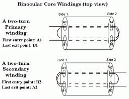
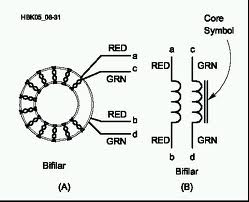
<20:25:54> "Todd K7TFC": I don't get making a transformer with bin. cores if
there's no coupling????
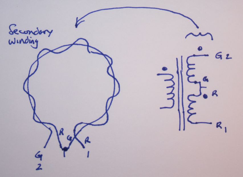
<20:26:32> "Joe N2CX": The coupling is between turns within each hole
<20:27:59> "Todd K7TFC": Wound bi/tri-filar?
<20:29:46> "Todd K7TFC": Got it!!!
<20:40:42> "Todd K7TFC": Could you clarify what A-sub-L characterizes?
<20:41:34> "Joe N2CX": Don't know the name for A sub L but it has units of uh or
mu per turn squared
<20:44:31> "Todd K7TFC": Fly-tying clamps might be good to hold small toroids.
Handheld Jewler's vises, too.
<20:48:29> "Joe N2CX": Soldereze is a trade name general term is heat strippable
insulation it is a plastic coating, not enamel
<20:49:52> "Joe N2CX": it is important also to tin the wire up to the core
<20:53:22> "Todd K7TFC": How important is evenly spacing the turns?
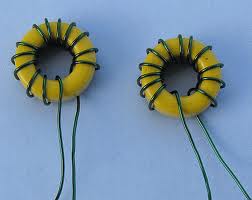
<20:55:35> "Todd K7TFC": The two yellow toroids just under "dreaded": is that
even enough?
<20:57:09> "Joe N2CX": Even spacing gives nominal inductance and the ability to
later spread or compress the windings to tweak exact inductance
<21:07:01> "Terry WB4JFI": Larry - try selecting another mic PTT key. I had that
happen using several different assigned keys
<21:10:51> "Todd K7TFC": Shouldn't the core symbol be between the pri. & sec.?
Does that matter?
<21:11:38> "Joe N2CX": Strictly speaking you are right. It's often left to the
imagination of the viewer if it is relatively obvious
<21:12:15> "Joe N2CX": In other words it depends on the symbol det in your
drawing package...
<21:16:38> "George - N2APB": Great to have you with us here tonight Nancy!!!
<21:17:22> "Todd K7TFC": I think rtv for aquariums doesn't have acetic acid. I
may be wrong.
<21:23:15> "Todd K7TFC": Is building the choke balun in a metallic enclosure
okay?
<21:23:54> "George - N2APB": Yep, but it will make a heavier assy ... remember
that the balun gets located up at the junction of the two legs of a dipole.
<21:25:00> "Todd K7TFC": Altoids tin, perhaps.
<21:25:28> "Nancy - NJ8B": George, I'm glad to be here too. Much depends on
Carolyn, but I'm very glad to be here. I finally figured out how to get
TeamSpeak to work.
<21:25:48> "George - N2APB": Ooops, oh yeah, you'd have to isolate the grounds
of each BNC connector for it to work right!! Sorry about that.
<21:27:22> "Joe N2CX": HI Nancy!
<21:29:41> "Nancy - NJ8B": Hi Joe!
<21:32:19> "Joe N2CX": unbalanced feed of a dipole is discussed in some detail
in the reference "Some Aspects of the Balun Problem by W2DU
<21:33:01> "Todd K7TFC": The best 90 minutes for the last week! Are George and I
the only ones vain enough to have a photo avatar?
<21:33:46> "Larry - W2HHV": I need to used a different PTT key.
<21:35:40> "Terry WB4JFI": grok
<21:36:00> "Joe N2CX": grokked! from Heinlein!
SESSION NOTES
Here is a handy project that illustrates many of the principles we've
covered this week ... the Choke Balun. When coax is used as a
feedline for a dipole, or other types of balanced antennas, it is ideal
to maintain the e-field inside the coax, between the center conductor
and the inner side of the coax shield. If some mechanism is
not present to prevent the signal from also traveling along the
outside of the coax shield, that signal will radiate and in general
present an unintended/undesirable match to the radio-antenna system.
This simple project provides a way to limit, or "choke" off the the
signal flowing along the outside part of the coax shield, thus
preventing the feedline from radiating, and thus you get more of the
intended signal to/from the antenna.

The N2CX Choke Balun consists of a toroid wound with 10-turns of RG-174
coax, located right up at the feedpoint of the dipole antenna. The
coax feedline connects to one side, and the legs of the dipole antenna
are connected to the BNC connector on the other side of the box (one
side of the antenna goes to the center conductor; the other side goes to
the "ground" side of the BNC connector.)

The schematic couldn't be simpler ... just strip and connect the ends
of the coax to the BNC connector on either side of the toroid.

We used a small plastic box from radio Shack ... any small, lightweight
enclosure would work equally well. (It'll be helpful to ultimately
make the enclosure water-tight to reduce the effects of changing
climates.

When connecting a BNC to a panel of some sort, a handy trick to do is to
use an old BNC adapter on the busy-end of the BNC connector being
attached so you don't bend/deform the barrel of the connector.
This also provides a handy way to grasp the connector while tightening.

Here's what the enclosure looks like with the two BNC connectors
installed.

This FT-114-43 core is 1.14" in outer diameter, and it has a
permeability mix of 43, which is quite suitable for our use at HF.

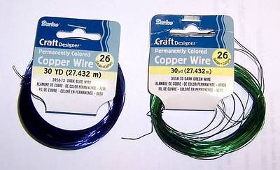
RG-174 coax is very handy to have on the workbench, as we make use of
about 20" here. It's lots easier to prepare the ends before you
start winding, rather than afterward.

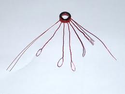
When putting the 10 turns of the coax on the toroid core, you count just
as with standard single-wire windings - each time through the core
counts as a turn.
You'll need to keep a firm grasp on the coax as you make the windings.

Then, when complete, use a tie-wrap or a piece of electrical tape to
hold the ends together.

Next, simple connect each end of the coax to the BNC connectors as you
would normally expect: center conductor to center pin, and shield to the
"ground" of the connector.

Tuck the
toroid down inside the box in preparation for buttoning things up.

But before you do close up the box, let's measure the actual inductance
of the choke.
IMPORTANT: Measure from the "ground/shield" sides of each BNC
connector ... after all, the coax's shield is actually the issue here,
right?!
With our handy-dandy AADE L/C Meter II (you DO have one, don't
you?!), we measure a shield inductance of about 44 uH.

Lastly
now, let's look at the result of using this choke balun in a coax
feedline to a dipole antenna being used on 80m.
We see that the reactive impedance resulting from the choke is 967 ohms
... which happens to be enough to stifle the RF current flowing all
along the outside of the coax
thus making our antenna system perform a whole lot better!