
(Now a bi-weekly program)
December 11, 2012
Join the "CWTD Yahoo Group" for
email discussion in between our weekly sessions by clicking
here.
dB or Not dB ...
Decibels and the Homebrewer
The Use and Benefits of Working with
Decibels in Ham Radio and on the Bench
(Note: This is the last
episode before the holidays!)
Overview
Decibels (dB, dBm, dBW, dBc, dBu) are useful concepts for homebrewing hams
to be comfortable with. When these terms come up in magazines and equipment
measurement/evaluation articles, we sometimes have trouble focusing on the real issue
if we are busy wondering whether 3 dB means a factor of 2 or 4 (or something
else). And when it comes to measuring your homebrew creation on the bench, the
dB readings become the universal language describing performance:
sensitivity, MDS, IMD, gain, LPF rolloff, and more. It is well worth the
effort to review these concepts from time to time and keep familiar with them
... and that's the nature of our CWTD show this time!
73, George N2APB & Joe N2CX
Audio Recording
... (Listen
to the MP3 podcast)
Discussion
Notes:
<20:03:59> "Alan W2AEW": Yikes - the Rohde & Schwarz app
note is 35 pages!
<20:09:54> "oh2nlt": Even TeamSpeak volume control is shown in dB scale !
<20:10:55> "Alan W2AEW": That modern s-meter is from a TS-870S
<20:14:05> "George - N2APB": Ha! You are right Juha!
<20:15:01> "Alan W2AEW": it turns multiplication and division problems into
addition and subtraction
<20:16:11> "George - N2APB": Ah yes, the R&S paper is indeed longer than the 3
pages I mentioned. Was thinking of an IMD Measurement paper I was thinking of.
Look at it this way ... 30 more pages of golden information!
<20:27:19> "Alan W2AEW": dBc is very common of course
<20:32:53> "George - N2APB": Juha, what was the test scenario of your 8594E
plot?
<20:38:01> "oh2nlt": left most spike is opposite sideband delta cursor show the
attenuated carrier which is -47.5dBc
<20:40:21> "Joe N2CX": Actually the spreading out of the display is a function
of the frequency span. Resolution bandwidth is filtering of the signals
displayed.
<20:40:32> "John ZL1AZS": This session is a useful way of reminding me of what I
don't know that I don't know :)
<20:43:09> "Alan W2AEW": actually, looks like it might have been a 625Hz test
tone, and you see that is +625Hz above the suppressed carrier, and the delta
marker is on the lower sideband which is -625Hz from the carrier, thus 1.25KHz
from the test tone
<20:45:37> "Alan W2AEW": looks like a nice attenuator - what's the frequency
range?
<20:46:00> "Alan W2AEW": oops, I see it is DC to 3GHz
<20:46:26> "Joe N2CX": Alan, good example of how you really have to watch the
settings and values to get the right interpretation!
<20:52:16> "Alan W2AEW": I've yet to measure a rig that has a true 6dB / s-unit
scale! Many are close at the top end of the scale, but much less per s-unit at
the low end of the scale.
<20:52:35> "Terry WB4JFI": I'm trying to find a spreadsheet that I created a
while back, that creates a one-page printout of dBm, power (Watts), Volts RMS,
Volts P-P, and S unit in 1dBm stepss. If I find it, I will send it to George.
<20:52:54> "Clint-ka7oei": Are "dBs" DeciBels's?
<20:53:14> "Clint-ka7oei": Decibels's
<20:53:31> "Alan W2AEW": or, is it dB relative to some quantity "s"
<20:53:44> "Alan W2AEW": ;-0
<21:26:08> "Ray K2ULR": Jan 8th
<21:27:01> "Ray K2ULR": 73
<21:28:34> "Frank N3PUU": thanks guys, great session as always.. if I dont talk
to you have a great holiday!
<21:29:16> "John ZL1AZS": Good Christmas and happy holidays to all!
<21:29:57> "John ZL1AZS": Is that Joe's workbench in the whiteboard?
<21:30:17> "Ray K2ULR": Merry Christmas to all.. and a happy new year!
SESSION NOTES
....
Decibels and the Homebrewer

From Wikipedia ...
The decibel (dB) is a logarithmic unit that indicates
the ratio of a physical quantity (usually power or intensity) relative to a
specified or implied reference level. A ratio in decibels is ten times the
logarithm to base 10 of the ratio of two power quantities.[1] A decibel is
one tenth of a bel, a seldom-used unit named in honor of Alexander Graham
Bell.
The decibel is used for a wide variety of measurements in science and
engineering, most prominently in acoustics, electronics, and control theory.
In electronics, the gains of amplifiers, attenuation of signals, and
signal-to-noise ratios are often expressed in decibels. The decibel confers
a number of advantages, such as the ability to conveniently represent very
large or small numbers, and the ability to carry out multiplication of
ratios by simple addition and subtraction.
A change in power ratio by a factor of 10 is a 10 dB change. A change in
power ratio by a factor of two is approximately a 3 dB change.
The decibel symbol is often qualified with a suffix, that indicates which
reference quantity or frequency weighting function has been used. For
example, dBm indicates a reference level of one milliwatt, while dBu is
referenced to approximately 0.775 volts RMS.[2]
The definitions of the decibel and bel use base 10 logarithms. The neper, an
alternative logarithmic ratio unit sometimes used, uses the natural
logarithm (base e).[3]
Some familiar representations of dB
?? ...


Don't worry
everybody gets confused now and then when dealing with decibels.
Definition
Decibel: A unit
used to express relative difference in power or intensity, usually between two
acoustic or electric signals, equal to ten times the common logarithm of the
ratio of the two levels.
Although the base
10 logarithm of the ratio of two power levels is a dimensionless quantity, it
has units of "Bel" in honor of the inventor of the telephone (Alexander Graham
Bell). In order to obtain more manageable numbers, we use the dB (decibel, where
"deci" stands for one tenth) instead of the Bel for computation purposes. We
have to multiply the Bel values by 10 (just as we need to multiply a distance by
1000 if we want to use millimeters instead of meters).

Incidentally 1 dB
increase in sound level represents approximately the smallest sound change that
the human ear can discern.
It may appear to be
confusing but by having units defined in terms of logarithms, multiplication and
division can be done using addition and subtraction.
For example, a 10
times increase in power is 10 dB, so if you have 1 Watt of RF and you amplify it 10
times, you have 10 times more power. If you attenuate it to 1/10th
the original power, you decrease by 10 dB.
Taking this idea a
little farther amplification by 100 times (10 times 10) results in an increase
of 20 dB (10 plus 10).
Important thing to
remember is that dB usage ultimately relates to either power ratios or absolute
powers.
Commonly dB as the
above definition says is that it is used to refer to power ratios.
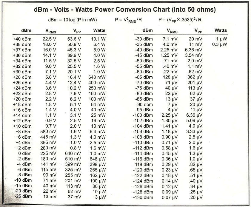
What does dBm Mean?
Similarly, when
dealing in RF,
dBm refers to a power level relative to 0 dBm or 1 mW into 50 ohms,
corresponding to 0.2236 mV rms.
At higher power
levels it's common to refer to 1 Watt into 50 ohms or 0 dBW.
Table of common
values showing dBm, dBW, rms voltage and rms power

Signal purity and dBC or dB
relative to a carrier
Spectrum analyzer
photos with a carrier and several harmonics


Note that
spectragraphs and equipment displays often represent the signals with a vertical
axis in dB. The major divisions are usually programmable, and more often
than not they are in 10 dB increments such as shown in the image on the right of
the HP-8561 spectrum analyzer.
On the left, one
can see many harmonics of the 21.75 MHz fundamental frequency being measured, as well as
other signals. The fundamental signal is usually the highest level
displayed, and the signals to each side of the fundamental exhibit smaller
levels (sometimes!), which are often indicated in terms of "dB down from the fundamental".
One the right, the
spectrum analyzer is showing a view of the fundamental frequency (14,00070 kHz)
being transmitted by an SDR Cube transmitter through the RF PowerCube amplifier.
With a close-in view of the signal (resolution bandwidth = 100 Hz), we can see
the opposite sideband level of the 1.25 kHz test tone showing as being -47 dB
... or "47 dB below the carrier".
Attenuators ... Essential in Test
Bench Measurement Equipment


.jpeg)
.jpeg)


Dynamic Range

Signal-to-Noise Ratio (SNR

S- units and dB
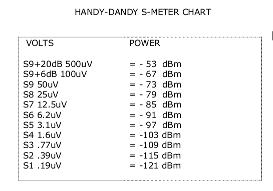
An S-METER is calibrated by connecting a signal generator to the
antenna terminal and setting the output power to 50uV, or -73dBm, and adjusting
the S-meter calibration pot for a reading of S-9. Since the S-meter is usually
derived from the receiver AGC line, it .is. relatively linear from about S3-S4
and upward (since a good AGC usually "kicks in" around
-100 to -105dBm). This linearity
is also due to the diodes used for the AGC detector, once they are conducting in
the linear region (again, around S3-S4). Statements that "S-meters are totally
worthless" or "a change in 2 S-units means nothing" are thus actually quite
incorrect. An S-meter .is. a fairly good RELATIVE power indicator for received
signal strengths and noise levels.
(From NA5N ...
http://www.gqrp.com/s_units.pdf)
A Typical (?) Test Bench
See
how many places dB's are used in these tests that N2CX and N2APB were making for
some SDR Cube IMD measurements ...
[Answer: 10 log (3765499 / 376549.9)]

Okay ... Now let's take a look at how all these components
connect together ... with dB's in mind!

Antennas – dB gain relative to
what?
DB gain
statement is meaningless without an appropriate reference.
dBi sometimes
used to refer gain to an isotropic antenna and this is ok for comparison of
antenna gains in modeling but is often misapplied in antenna advertising as in
http://www.w8ji.com/antennas.htm
Excerpt from
W8JI work:
dBd vs dBi
The dipole is the basic building block of many
antennas. A dipole does NOT have 2.2 dB gain over an isotropic radiator when
the dipole is placed over earth. The dipole has about 8.5 dB gain over an
isotropic radiator! Always remember this when you see antenna models over
earth given in dBi. If the model over earth shows a "gain" of about 8.5 dBi,
the model effectively has the same gain as a dipole.
Here is the
pattern of a 145-foot high copper wire dipole over medium real earth on
EZNEC:


You can see
the gain is 8.5 dBi, and it is
just a simple dipole just over 1/2 wave high. Any antenna you model should
always be compared to a standard like this!
The notion a
dipole has around 2.15 dBi gain is only true for freespace.
Relative antenna test - hams set
up impromptu antenna test ranges to compare antennas:
VHF/UHF antenna
shootouts

Refs for
antenna testing
www.qsl.net/n1bwt/chap9.pdf
HFPack HF antenna
shootouts ...
http://hfpack.com/antennas/
The
purpose of the HFpack Pedestrian Antenna Shootout is to try out a
variety of pedestrian antennas, measure and document the antennas in a
well-controlled manner, and report the results as a service to radio
operators around the world interested in furthering the state - of - the
- art for HF portable.
1. All antenna entries should be physically present to register at the
HFpack Shootout site, Pacificon Convention, at 11am on Sunday, 20
October 2002.
2. The antenna shootout is for "Pedestrian Antennas". A pedestrian
antenna is considered to be a lightweight antenna that can easily be
carried to the shootout by one person in a backpack or bag. It is not
necessary to walk around carrying the antenna while in operation. The
shootout is not intended to include heavy antennas designed mainly for
base station operation, thus, antennas exceeding 11 pounds are
discouraged from entry.
3. The test transmitter has a feedline with a 1:1 balun/unun at the
feedpoint. The test feedpoint (antenna mounting point) is elevated above
ground level, and provides a BNC, SO-239, or 3/8-24
female threads, or terminal lug to connect the antenna to. The balun has
at least 20dB of isolation at 14MHz.
4. During the RF measurement, the test transmitter delivers about 5
Watts CW into the entry antenna for about 30 seconds.
5. For vertical quarterwave whips, the feedpoint has a single
quarterwave resonant "radial" counterpoise, sloping down at about a 45
degree angle in the direction of the test receiver site. No other
counterpoise will be used for quarterwave whips.
6. Since the objective is to remove any extraneous variables from the RF
measurement, the standard antenna test fixture will be used for all
antennas. So no other feedline will be used, and it is not necessary
of desirable for the entry antenna to include a support pole, since the
support is provided by the test fixture.
7. Commercial antenna manufacturer personnel may not participate as part
of the HFpack Shootout engineering measurement team, however they are
invited to be present and help set up their antenna on the test fixture.
8. The only frequency of the shootout is 14.1MHz (+/-10kHz).
9. Antennas will be physically measured (inches), weighed (pounds),
photographed (digital), and tested for radiated RF on the test range.
The results of the tests, measurements, photographs, and description
of the antenna may appear on the HFpack website or other publications.
10. Antenna RF radiation will be measured by a calibrated test receiver
using linearly polarized small antenna on an elevated support pole. The
test receiver antenna will be operated first in vertical and
then in horizontal polarization. The entry may enter appropriately in
either the horizontal or vertical polarization category.
11. Horizontally polarized antennas and vertical antennas not requiring
a counterpoise will be elevated to 16 feet at the feedpoint or radiation
center.
12. Antennas should self-match to 50 ohms nominal impedance.
13. Antenna owners who are not present may privately arrange for another
person to enter their antenna.
14. A commercial antenna may be entered by anyone who owns it, however,
multiple entries of the same type of commercial antenna by different
owners is discouraged.
15. The general public, amateur radio operators, volunteer witnesses,
and others will be present to view the shootout.
16. Other guidelines may be posted or verbally announced or personally
advised at the shootout.
17. Requests to test an antenna using other than the standard
test fixture and methods will probably be rejected unless there is a good
and compelling technical reason to do so.
18. In the unlikely event of confusion or dispute, a panel of 3 HFpack
members chosen by the HFpack members present at the shootout will
attempt to resolve the issue in an amiable manner.
Mobile antenna
shootouts:
http://www.k0bg.com/shootout.html
-
Treatise by NA5N ...
http://www.gqrp.com/s_units.pdf
-
Other S-unit vs dBm table ...
http://www.astrosurf.com/luxorion/qsl-db-power-units.htm
-
Wikipedia ...
http://en.wikipedia.org/wiki/Decibels
-
Mobile antenna
shootouts:
http://www.k0bg.com/shootout.html
-
HFPack HF antenna
shootouts ...
http://hfpack.com/antennas/
-
Antenna testing
www.qsl.net/n1bwt/chap9.pdf
-
Decibel
Measurements (R&S) ...
PDF
-
An Excel spreadsheet that prints dBm, Power, Volts
RMS, Volts Peak, and S units ... by Terry Fox, WB4JFI
Back to CWTD Home