(Now a bi-weekly program)
September 17, 2013
Join the "CWTD Yahoo Group" for email discussion in between our bi-weekly sessions.
Analyze This! ... Two-Tone Test Oscillator
Uses of a 2-tone test oscillator and the inner workings of the Elecraft mini-module
Overview
We continue our popular "Analyze This!" type of program this time with a description of a popular, inexpensive and extremely useful two-tone test oscillator from Elecraft, called the 2T-gen.
In this episode we overview the basics of two-tone testing, and very quickly get to the Elecraft 2T-gen circuit to break it down and analyze its functions. With actual, documented experience of using it on the bench, we show the benefits of performing the procedures for IMD and PEP measurements to give CWTD members another powerful tool in their arsenal of test equipment for the bench.
73, George N2APB & Joe N2CXPodcast ... Right-click to download & listen!
Text Chat window from during the show ...
<20:09:57> "Rick K3IND": Why not use just one tone?
<20:14:37> "Alan W2AEW": Here's a video I did on two tone testing: http://www.youtube.com/watch?v=3DxBg6h4Fc8
<20:25:35> "Alan W2AEW": As you probably know, the early HP sine wave oscillator used an incandescent bulb as a non-linear element in the feedback to adjust the gain
<20:27:56> "Eamon - VE2EGN": I had an old tube audio oscillator with a light bulb. I didn't understand what it was for at the time.
<20:27:59> "Alan W2AEW": I was typing it just before got to that part of the story!
<20:31:52> "Laz K2LAZ, FN20": got to go early; thanks i will get a fill on the recording.
<20:35:54> "Eamon - VE2EGN": So the AGC starts limiting as soon as the Q1/Q3 base starts conducting. The "nominal" setting for 1:1 feedback gain has R9 or R3 in series with the MOSFET, equal to R7 or R1 i.e. 6.8k, so it sets the gate voltage to the level needed to make the channel resistance equal to about 3.5k.
<20:38:25> "Alan W2AEW": The MOSFET is being used as a voltage variable resistor to adjust the gain
<20:38:45> "Eamon - VE2EGN": It needs a very precise gain setting to give a pure sine wave.
<20:39:03> "Alan W2AEW": exactly right
<20:39:04> "Eamon - VE2EGN": The only way to get a gain of exactly 1 is to adjust in a feedback loop.
<20:40:14> "Alan W2AEW": this is how the bulb worked in the original circuit. As the signal level rose, the filament resistance would change, thus changing the gain.
<20:42:25> "Rick K3IND": So ground is no longer the reference for the circuit...
<20:43:00> "Eamon - VE2EGN": Ground can be whatever you want it to be... I usually think of a VCC/2 reference as a "virtual" ground.
<20:51:36> "Eamon - VE2EGN": You seem to be saying IMD = -30dB although the product is about 25dB down. Oh... could this be because you need to sum the two tones as the reference level?
<20:52:33> "Eamon - VE2EGN": I guess the *peak* level is 6dB higher than each component's RMS.
<20:52:48> "Joe N2CX": Yeah Eamon that is correct!
<20:53:58> "Eamon - VE2EGN": It's an envelope, with illustrator's license (from a manual)
<20:54:39> "Jack WA9FVP": looking at the schematic I can see that Q2 and Q4 sets the level. The Utube video I mentioned shows a simple light bulb in the same place http://www.youtube.com/watch?v=vBsSASge7ls
<20:56:05> "Jack WA9FVP": can you call that the "power bandwidth" ?
<21:07:58> "Alan W2AEW": try this; http://w4neq.com/pdf/ssb_im.pdf
<21:09:20> "Pete - WB2QLL": A computer sound can be used to generate two tone tests. A couple I know of are: http://ko4bb.com/ToneGenerator/ , http://www.weaksignals.com and pick TCUBE from the menu on the left. These do other functions as well, and as far as I know are free.
<21:09:41> "Jay K4ZLE": yep, went to his web site and came in the back door so to speak and it is available. Tnx
<21:14:14> "Rick K3IND": $59
<21:15:06> "Eamon - VE2EGN": Nope, but I'd like to know how good it is compared with vintage HP.
<21:15:38> "Alan W2AEW": should be fine - just check the SFDR specs to be sure you don't generate intermods internally
<21:15:58> "Alan W2AEW": that would be RBW (not VBW)
<21:20:07> "Jay K4ZLE": george Stebenthaler (SP) had good article on HB spectrum Analyzer that does the job for me on HF and only cost me abt $100 to make. USB connected to PC and can save pix, etc.
<21:20:29> "Jay K4ZLE": Article was in QST few yrs back
<21:21:59> "Armand WA1UQO": As always guys - great program. Learn something each time! Thanks for your efforts - Much appreciated.
<21:22:08> "Frank N3PUU": thanks guys, great show!
<21:22:46> "Jay K4ZLE": Eager to see more on FreeSOC, maybe next time?
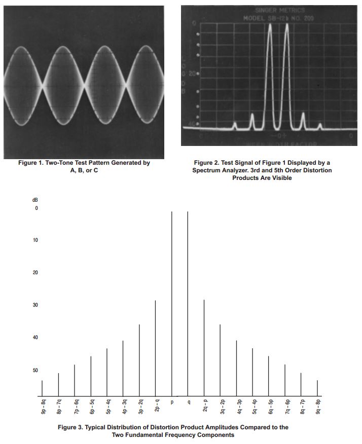
Two-Tone Test Signals
When it comes to transmitter, amplifier or balanced modulator tests, you need a device generating two non-harmonically related frequencies in the audio band ... this equipment is known as a two-tone test oscillator. The frequencies used in this oscillator are around 720 and 1900 Hz, located well inside the audio passband of any SSB circuit. Two Wien oscillators are often used, having low harmonic content and convenient controls for level and balance.
Used to test RF PA intermodulation distortion in an SSB transmitter
700 and 1900 Hz audio tones used for intermod testing of linear RF power amps
Intentionally not harmonically related
Tones are adjustable to get equal levels in RF output display
The Elecraft 2T-Gen ... http://www.elecraft.com/mini_module_kits/mini_modules.htm
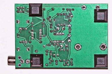
Very useful, handy and inexpensive Mini-Module kit ...One-night to build with average soldering skills
Uses discrete through-hole components on a small printed circuit board
Front and back pictures of the Elecraft 2T-gen
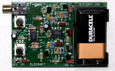
Operates from an on-board 9V battery
On-board level controls
Output is an RCA phono jack
Circuit description

Two wein-bridge audio oscillators
Identical except for frequency determining components
Uses two two-section LMC6482AIN op-amp chips
One section U1B is the 700 Hz oscillator
Frequency determined by feedback on the positive op-amp input
Wein Bridge RC circuit C6/R8 and C8/R12 feeds positive input from the output
Oscillator level set by resistors R7/R9 and an AGC circuit
Op-amp output feeds bipolar transistor Q3 which set up as a half-wave detector
Q3 output is a DC level filtered by capacitor C5.
Resulting DC biases the gate of MOSFET transistor Q4.
Q4 acts as a variable resistor to provide negative feedback to set oscillator level
Increases in oscillator level result in a lower bias on the FET.
This increases the FET channel resistance increasing negative feedback, stabilizing the output level
U1 uses same circuit topology
R2 and R6 are different in value tuning the Wein Bridge circuit to 1700 Hz.
Jumpers JP1 and JP2 allow selection of one or both oscillators.
Oscillator outputs are summed via resistors and balancing pot R21
Op-amp section U2B provides a buffered output.
C9 is a DC decoupling cap
R18 and R19 give output level adjustment.
DC power comes from a 9 volt battery with a switch and power indicator D1
Op-amp U2A and resistors R13 and R14 provide a low impedance 4.5 volt bias for the other circuitry.
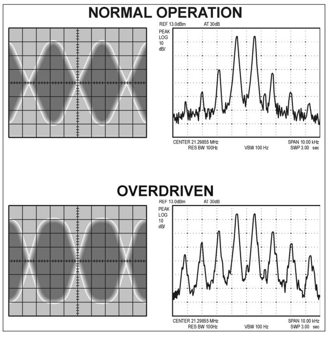
Envelope and Spectrum Analyzer Displays (from page 6 of Elecraft 2T-Gen manual)
IMD Measurement Discussion
Reference the good paper Motorola EB38: Measuring the Intermodulation Distortion of Linear Amplifiers
The measured distortion of a linear amplifier, normally called Intermodulation Distortion (IMD), is expressed as the power in decibels below the amplifier’s peak power or below that of one of the tones employed to produce the complex test signal.
A signal of three or more tones is used in certain video IMD tests, but two tones are common for HF SSB. The two-tone test signal provides a standard, controlled test method, whereas the human voice contains an unknown number of frequencies of various amplitudes and couldn’t be used for accurate power and linearity measurements.
Separation of the two tones, for voice operation equipment, may be from 300 Hz to 3 kHz, 1 kHz being a standard adopted by the industry
... W2AEW ... http://www.youtube.com/watch?v=3DxBg6h4Fc8
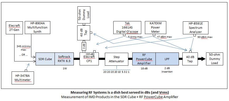
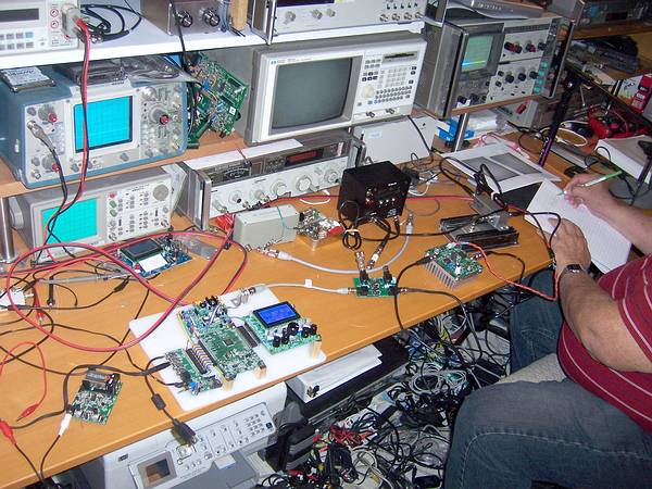
Testing IMD on the RF PowerCube N2CX and N2APB in George's lab
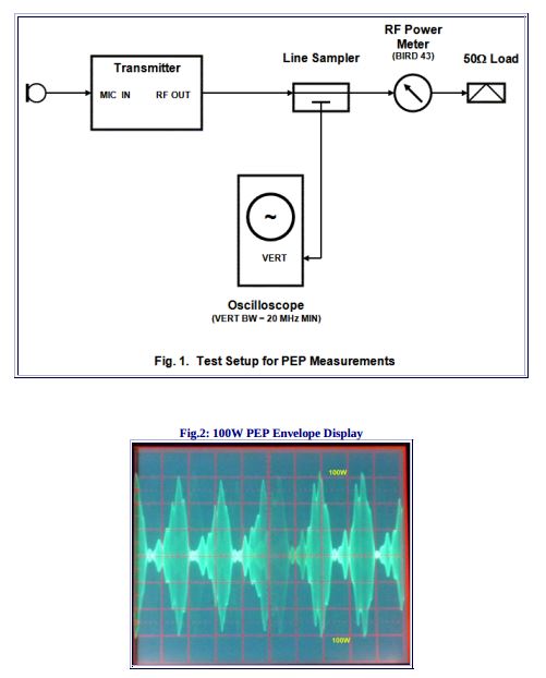
PEP discussion
See excellent 2-page SSB PEP Measurement Procedure ... http://www.ab4oj.com/test/peptest.html
Definition of PEP: Peak Envelope Power (PEP) is the average power supplied to the antenna by a transmitter during
one radio-frequency cycle at the crest of the modulation envelope taken under normal operating conditions.
In RF power metrology, the Crest Factor (CF) is defined as the ratio of PEP to average power. Thus, CF = PEP/Pavg
In the CW modes (CW, RTTY, FM), CF = 1.
In SSB, depending on voice characteristics, average power may run 50% to 65% of PEP (CF = 1.53 to 2).
In properly-adjusted AM, average power at 100% modulation = 1.5 X resting carrier power, and PEP = 4X resting carrier power, i.e. CF = 2.66.
The oscilloscope is a far more accurate PEP measuring tool than even a "peak-reading" RF power meter, as it will
display the crest (peaks) of the modulation envelope independently of the rise-time, audio-frequency response or spectral
distribution (power density) of the transmitted signal
References:
- HP EB38 MEASURING THE INTERMODULATION DISTORTION OF LINEAR AMPLIFIERS ... http://w4neq.com/pdf/ssb_im.pdf
- ARRL lab methods ... available from www.arrl.org
- A Simple PEP Measuring Procedure ... http://www.ab4oj.com/test/peptest.html
- Two-Tone IMD Measurement Techniques, RF Test & Measurement (Barkley) ... https://www.macomtech.com/static/PDFs/TechnicaArticles/RFcharacterization.pdf
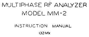
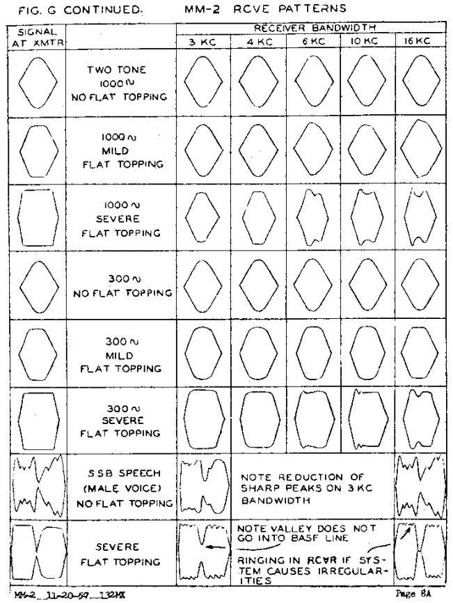
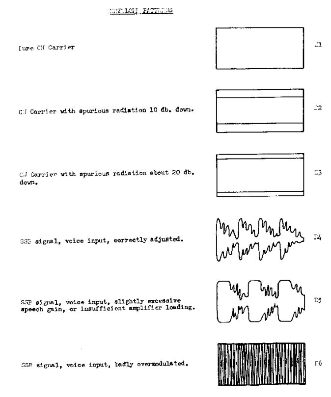
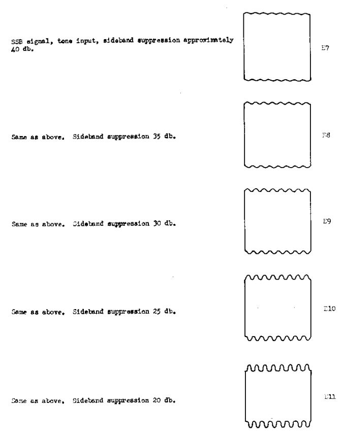
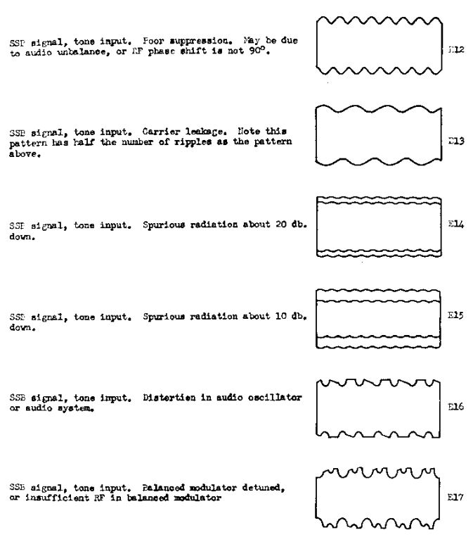
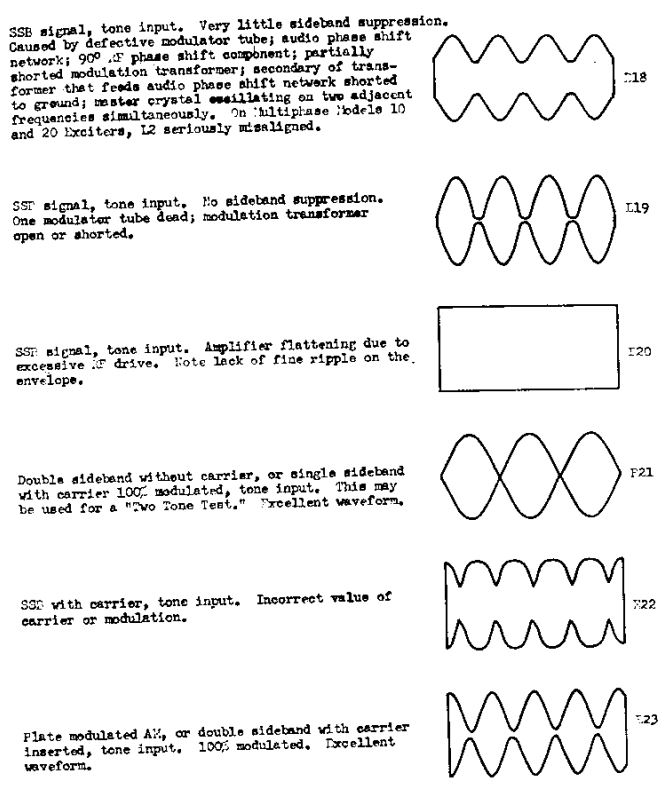
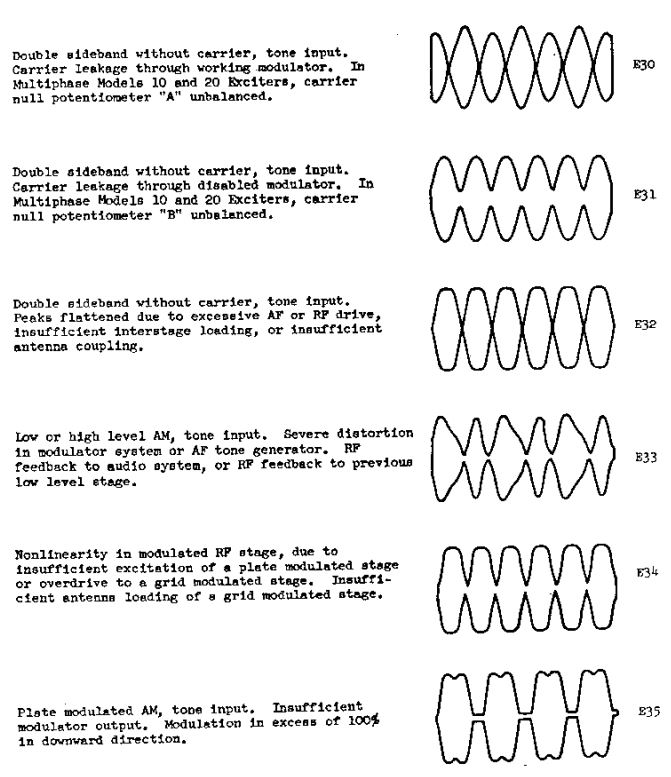
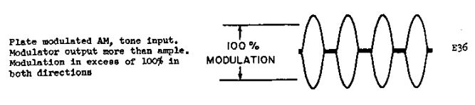
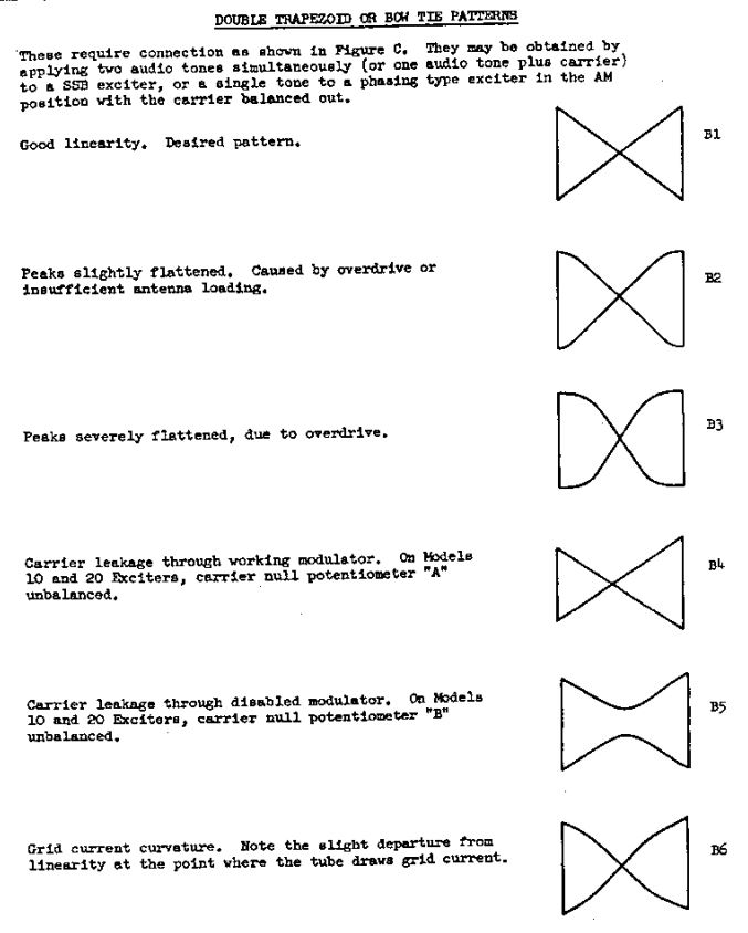
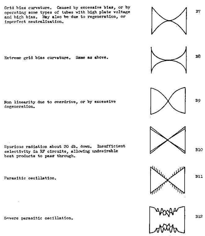
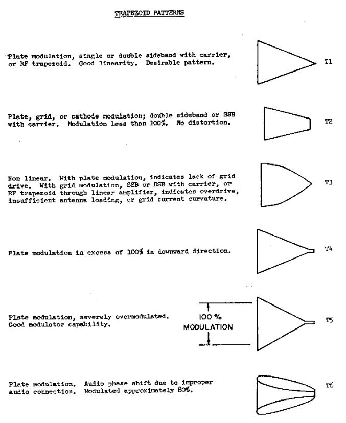
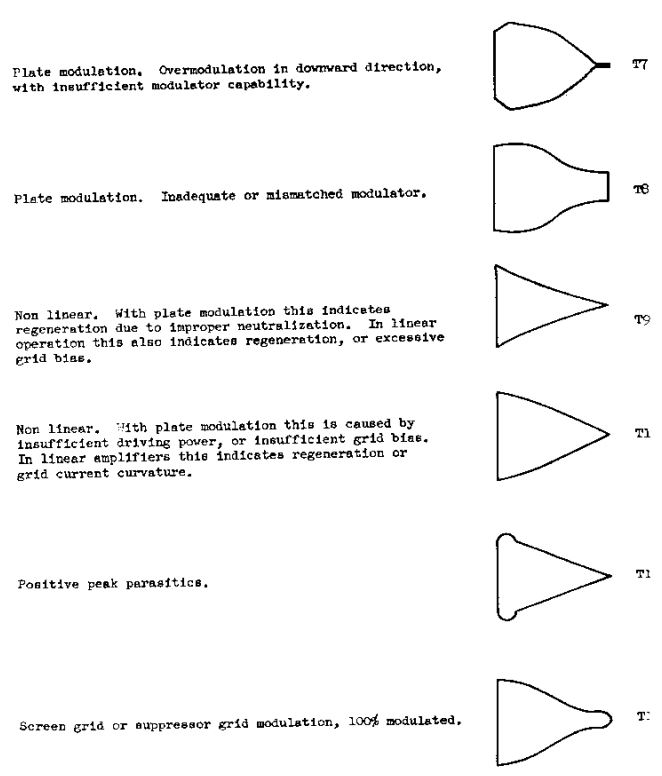
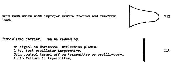
APPENDIX: Scope Patterns from the Central Electronics "Multiphase RF Analyzer MM-2" manual circa 1956
http://bama.edebris.com/download/ce/mm2/mm2.pdf
GREAT reference for test patterns seen on a scope with a 2-tone input signal to an exciter/transmitter.
They cover an amazing number of problems!
... Thanks to Pete WB2QLL