
August 9, 2016
Elmer 101
and the Small Wonder Labs SW30+ Transceiver
Installment #6 ...
Rx Product Detector & Audio Preamp
and ... "Anatomy of a Homebrew Station"
A step-by-step analysis and build-up of the classic 2-watt 30-meter superhet transceiver
from designer Dave Benson K1SWL of Small Wonder Labs.
Overview
We're closing in on the completion of the SW30+ build-up! This time we take the output of the crystal filter and mix it down to audio baseband in order to get the CW tone we hear in our headphones.
So with this episode we'll start continue studying the Big Picture seen in the diagram "Anatomy of a Homebrew Station", and then "zoom in" on a couple of accessories (DSP audio filter and a simple keyer) as they are being built-up by intrepid homebrewers.A couple of BIG ANNOUNCEMENTS happen in this episode! ...
1) We are announcing a Contest for SW30+ Kit owners to strut their stuff! Over the course of the next couple of months we challenge the kit builders to do their best, and be judged in three categories: best original packaging, best packaging in the red pcb enclosure, and best accessorization. Some cool prizes are being offered ... The Contest Details page has all the details!
2) Live Video Feed! In this episode we are broadcasting a live video feed via the Zoom conferencing tool ... at the same time as using our ever-faithful Teamspeak audio client. Using the same computer that you're using for Teamspeak, or even using a second computer/smartphone/tablet, visit https://zoom.us/j/216305883 and let Zoom set things up for you. If all goes right, you'll see one/both of your friendly hosts as we show live views of the projects during the show. Just put your Zoom client on mute and watch the show, as you listen and speak on the show using Teamspeak per usual. Pretty cool, eh?!
BTW, did you say you missed the last episode? You can download the podcast and catch up on things at any time! The whiteboard material and audio recordings for all shows are listed right there on our home page! (www.cwtd.org)
Chat Discussion During Show ...
<20:29:04> "Alan W2AEW": I see you've got the Laserbeam DSP audio filter coming up on the whiteboard. I just got one of these, and plan on putting a video review together in the weeks to come...
<20:33:35> "Alan W2AEW": servo tape
<20:36:59> "Joe N2CX": SOTA DSP filter $32.3* (US) + shipping http://www.sotabeams.co.uk/dual-bandwidth-filter-modules-ssb-cw/
<20:39:06> "Pete wb2qll": SOTA also makes a variable width audio filter at US$49: http://www.sotabeams.co.uk/variable-bandwidth-filter-modules-ssb-cw/
<20:39:59> "Joe N2CX": Thank Pete, the one I showed was the first "hit" on Google.
<20:47:22> "Alan W2AEW": You can use just one output if you want to drive a grounded load. Leave the other open
<20:53:24> "Alan W2AEW": I have a video tutorial on the Gilbert Cell mixer (like in the NE602/SA612). The tutorial can be found here:
<20:53:26> "Alan W2AEW": https://www.youtube.com/watch?v=7nmmb0pqTU0
<21:05:21> "Obe - KC4VZT": Good night and thanks for another good show, loved the video.
(Click here if you want to get straight to the Elmer 101 feature material farther down the page)
Anatomy of a Homebrew Station
Here is a powerful block diagram representing the many varied possible "accessories" that we homebrewers have available to us in one form or another.
An interesting aspect of this diagram, however, is that all these accessory functions can be integrated quite nicely with the SW30+ rig ... or just about any other one!
Another interesting perspective, that will be explored in greater depth in numerous future episodes of CWTD is the "project" nature of these components.
(Envision, if you will, that each of these accessory functions can_and_will be fully designed and chronicled within the CWTD Projects section of our website!)
Further, this diagram becomes a "clickable roadmap" that links each item represented here to the respective project on the CWTD website.
So ... Try clicking on the images below! ... Soon we'll be populating each one of the pages linked in the diagram to actual, in-progress projects that we all can build and use!

N2CX Bench Tips
1. Effect of spacing of L1 turns (SW30 VFO)
As turns are spread or compressed on toroid, self capacitance changes tuning.
As first wound, tuning range was 2.430 to 2.463 MHz
With turns compressed it was 2.385 to 2.417 MHz
With turns spread out it was 2.445 to 2.478 MHz
Total adjustment range by adjusting turns layout was 60 kHz
2. Use the KX3 to check VFO frequency of the SW30
The KX3 tunes from below AM broadcast band to 30 MHz (and 50 - 54 MHZ)
Set Mode to CW with "wide" bandpass. Use tuning in 100 Hz steps
Run 18 in. insulated wire from the KX3 antenna jack and lay it alongside SW30 transceiver pc board
Tune the radio until loud beat note heard - it helps to know approx. frequency
Accessory Review ...
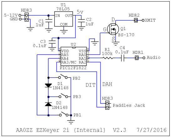
1) AA0ZZ EZKeyer 2i (Internal) ... Perfect for the SW30+ in either the Primary or Accessory enclosure

2) SOTABEAMS "LASERBEAM" DSP Audio Filter ... http://www.sotabeams.co.uk/dual-bandwidth-filter-modules-ssb-cw/
The new range of ready-made LASERBEAM-DUAL digital audio filter modules are the perfect addition to your project or even to your existing radio. Unlike analogue filters, digital filters provide near-perfect characteristics. Because of the way that they are implemented, they are better than analogue filters in almost every way!
LASERBEAM-DUAL Modules have been designed for ease of use. Each module has two filters onboard. There are three combinations to choose from:
The General Purpose module has a narrow CW filter (550 - 850 Hz) and an SSB filter (300 - 2700 Hz)
The CW module has two narrow filters (550 - 850 Hz) and (300 - 1300 Hz)
The SSB module has a standard SSB filter (300 - 2700 Hz) and a narrow SSB filter (300 - 2400 Hz).


CWTD Episode #83: Elmer 101 and the SW30+ Transceiver ... Rx Product Detector & Audio Amp
First, a few Notes:
Kits & boards are sold out.
Blank enclosure kits are available from Craig AA0ZZ.
FreqMite Kits now from 4SQRP ... And AA0ZZ shows here how to connect it to your SW30.
Accessories in progress ... Keyer Kit, Display, Arduino control, Spectrum output
For the latest & greatest SW30+ Kit information, see/download the Updated Manual
Block Diagram
Technical Discussion


Once again we borrow from the nicely-done Elmer 101
materials created for the community circa 2000 by David Ek, NK0E
in part 6 of
The Eks Files ... http://eksfiles.net/elmer-101-kit-building-materials/.
(And by the way, if you are interested in some excellent "op amp active
filter" discussion that directly relates to these specific circuits, we
urge you to look at Dave's full Part 6 installment referenced above.)
First, the Product Detector ...
The SW+ product detector circuit uses an NE602 for the mixer just like we’ve seen before. Here, the input comes in from the output of the 7.68 MHz crystal filter to pin 2. R1 is used to load the output of the filter to match it to the input impedance of the mixer. Since pin 1 isn’t being used it’s tied to ground through a capacitor (C104).
Crystal Y4 and capacitors C16, C17, and C18 makeup the frequency-determining components for the BFO. C16’s purpose is to pull Y4 up a bit in frequency just like RFC2 pulled the transmit LO down.
The output is taken from the mixer in a balanced configuration. The capacitor across pins 4 and 5 is there to allow the RF parts of the mixer output to pass freely, effectively removing it from the AF signal input to the audio amplifier stages.

The output of U3, another mixer, has a signal in the audio range that we can see on a scope or simply hear with sensitive headphones or an amplified speaker (use a DC blocking capacitor).
If previous stages are working but you aren't getting audio here as expected first check to be sure U3 is properly oriented and all the pins properly seated into the socket. Next get out your frequency selective RF signal tracer. A general coverage receiver that tunes to the IF frequency (7.68 MHz) will do nicely.
Temporarily unkey the transmitter that we have been using as a test signal so that signal source is turned off. Look for the BFO oscillator running around pins 6 and 7 of U3. If you can't find it, check Y4, C17 and C18 for proper soldering and values. Make sure W1 is in place next to Y4 where the board is labeled C18.
If you have the BFO running but still no audio out, start looking around pin 2 of U3. Key the transmitter on and off, you should hear the test signal in your general coverage receiver going on and off very near the BFO frequency. When done testing be sure to leave the transmitter keyed (jumper on J3 pins 1 to 3).


Next, the Audio Frequency Preamp...
The SW+ first-stage audio amplifier is configured as a low-pass filter. The RC low-pass filter is made up of R4 and C22 (8 volts DC bias is applied to the noninverted input of the op amp through R4). C23 and R7 in the feedback from the output to the inverting input also serve to filter out high frequencies.
C19 provides a “short” for high frequency components at the output of the product detector. C20 and C21 are DC blocking capacitors, and R2 and R3 limit current input to the amplifier. Diodes D3 and D4 limit the voltage swing of the output so Q1 (the FET which mutes the receiver during transmit) is not driven to saturation.
12 volts is applied to the V+ input, while the V- is grounded. The 8-volt DC bias on the input serves to put the signal voltage between V+ and V-.

This half of U4 amplifies the audio signal. It should be louder with an audio tracer. If this is not the case check to be sure U4 is plugged into the socket properly. Verify 7 volts or so on pin 8. Using your audio signal tracer listen for a tone at pins 2 and 3 of U4. There should be a little something on each, a bit louder on pin 2. Pin 1 should be noticeably louder than 2 or 3, if not check all the component values and proper soldering. Also refer to voltage checks on page 17 of the original SW30+ manual.


Spectrum View
Mike WA8BXN looked
at audio spectrums using a soundcard oscilloscope. Here is where he obtained the free one that he's been using for some number of years: https://www.zeitnitz.eu/scope_enInput to the SW30+ antenna connector was the same noise generator used above.
Audio coming out of the product detector viewed at R2 ...

Troubleshooting Schematic
.JPG)